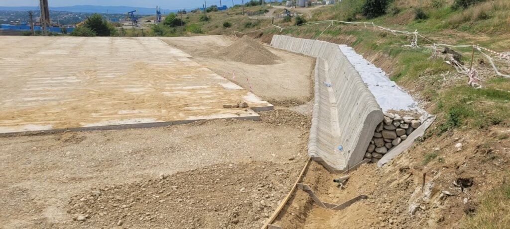
Drainage channels and retaining-wall components can both use non-standard concrete geometry, but they solve different engineering problems. Printing may simplify the forming of a custom shape; suitability still comes from the hydraulic, structural, geotechnical, durability, handling, and installation design.
Drainage components start with hydraulic performance
A channel profile should be sized for the actual flow, slope, roughness, freeboard, inlet and outlet conditions, transitions, sediment, erosion, blockage risk, and maintenance access. Curved or non-standard sections are useful only when the hydraulic design shows a clear benefit.
For channels in pedestrian or vehicular areas, EN 1433 may apply and the load class must be established. The specification may also need to cover the foundation, soil or traffic loads, joints, watertightness, freeze-thaw exposure, deicing salts, chemical exposure, abrasion, installation, and connection to the wider drainage system.
Retaining components are part of a soil-structure system
A retaining element is verified together with the ground, water, backfill, foundation, and connections. Typical checks include earth and groundwater pressures, surcharge, seismic actions where relevant, sliding, overturning, bearing resistance, overall stability, deformation, cracking, durability, drainage, lifting, transport, and installation.
Eurocode 7 provides the geotechnical framework and Eurocode 2 covers concrete structural design. EN 15258 and the common rules in EN 13369 may be relevant to conventionally manufactured precast retaining-wall products. For an additively manufactured component, the project team should confirm the current Romanian adoption, product route, and acceptance plan.
Reinforcement follows the design actions
Compressive strength alone does not determine reinforcement. Depending on cracking limits, handling loads, exposure, geometry, and interfaces, the solution may use conventional bars, fibres, prestressing, post-installed reinforcement, reinforced infill, or another verified strategy. Fibres can contribute to performance but do not automatically replace designed bar reinforcement.
Layered deposition can create directional properties and distinct interlayer interfaces. Material and component testing should therefore represent the production orientation, reinforcement arrangement, and relevant failure modes.
From design to release
- Set the design basis. Define the intended use, design actions, hydraulic or geotechnical inputs, exposure, service life, interfaces, installation, and applicable standards.
- Develop the production method. Coordinate the material, toolpath, reinforcement, embedded items, joints, lifting details, and trial requirements.
- Print and cure. Monitor the agreed process parameters, record interruptions or deviations, and apply the specified curing regime.
- Confirm handling strength. Release lifting, storage, transport, and installation only after the handling criteria are met.
- Inspect and accept. Check dimensions, visible condition, material properties, interlayer quality, reinforcement or embedded items, and the project-specific hydraulic, watertightness, durability, or load tests.
What to provide for project screening
- For drainage: hydraulic design basis, load class, geometry, joints, exposure, installation, and maintenance requirements.
- For retaining systems: structural and geotechnical basis, groundwater and drainage assumptions, reinforcement concept, connections, and handling requirements.
Layer By Layer Construction can use this information to assess printability, production development, and the evidence needed for release.
Contact us to discuss a defined component and its requirements.
Sources
- ISO/ASTM 52939:2023: qualification principles for additive construction.
- European Commission JRC, Eurocode 2: concrete structural design framework.
- European Commission JRC, Eurocode 7: geotechnical design framework.
- Bulgarian Institute for Standardization, EN 1433 project reference: scope of the drainage-channel product standard for pedestrian and vehicular areas.
- BSI, EN 15258 retaining-wall elements and The Concrete Centre, European precast standards: retaining-wall and common precast rules.
- FHWA, Introduction to Highway Hydraulics: hydraulic parameters used in channel analysis.
- Surehali et al., anisotropy in additively manufactured concrete: directional properties and interlayer behaviour.
Standards can be updated or adopted nationally with additional provisions. The current requirements should be checked for the actual project and place of use.