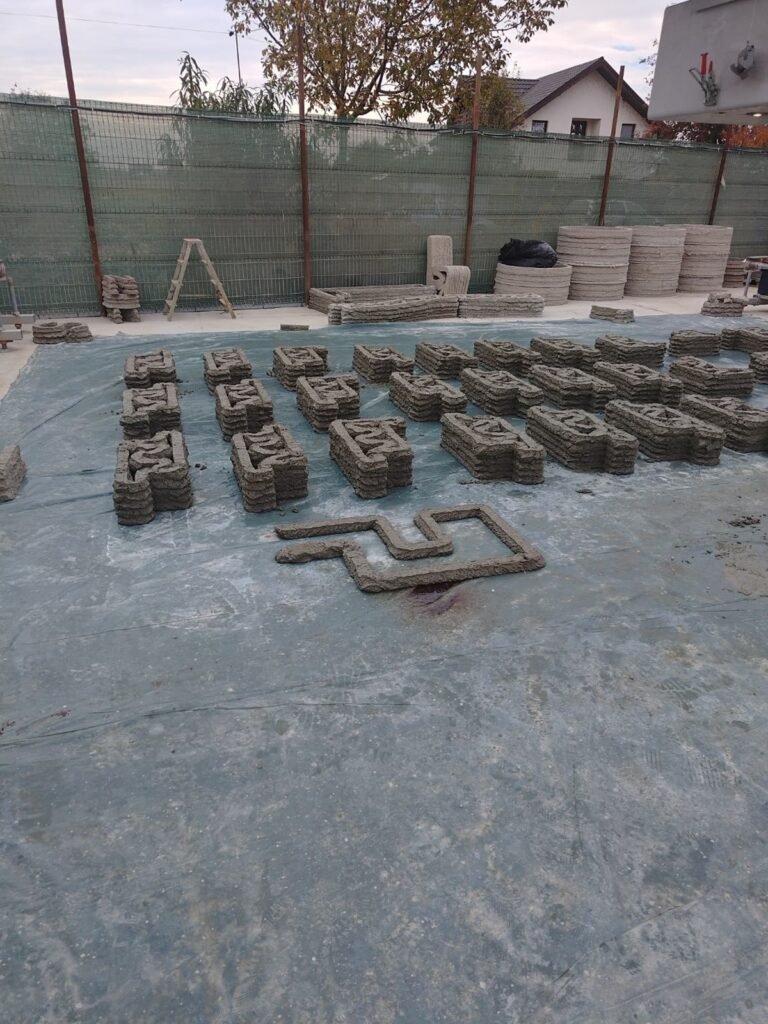
Channels, trench components, transitions, and drainage parts are good candidates for 3D-printed prefabrication when a project needs non-standard geometry or controlled variation. The process is less compelling when an established product is already made efficiently with reusable moulds.
Layer By Layer Construction produces with a COBOD BOD3, a rail-mounted mobile gantry system for construction-scale printing. The machine creates the geometry; the component still needs a defined design basis, material specification, reinforcement strategy, inspection plan, and release criteria.
Where the process can add value
- Channels and gutters: repeated or variable profiles for stormwater or industrial drainage.
- Trench components: utility or drainage parts adapted to cover, connections, handling, and site conditions.
- Transitions and connection pieces: changes in width, slope, profile, or interface that would otherwise need dedicated tooling.
- Special geometries: curved, tapered, textured, or project-specific components produced in limited or variable series.
Suitability is assessed at component level. The brief should define the intended use, design actions, exposure, dimensions, joints, lifting points, reinforcement, installation, and acceptance criteria before the toolpath is prepared.
From digital model to released component
- Coordinate the design. Confirm geometry, interfaces, tolerances, structural and hydraulic inputs, and the applicable approval route.
- Review production. Check wall thicknesses, radii, openings, layer orientation, reinforcement, embedded items, joints, lifting, storage, and transport.
- Prepare and qualify the toolpath. Define slicing, deposition sequence, trial pieces, specimens, and any component tests.
- Print and record. Track the agreed material batch, environmental conditions, machine settings, interruptions, and deviations.
- Cure and handle. Apply the specified curing regime and release lifting or transport only after the handling criteria are met.
- Inspect and release. Compare dimensions, visible condition, reinforcement checks, and test results with the documented acceptance criteria.
Quality records that support release
A useful production record links the approved model to the toolpath, material batch, process settings, curing, dimensional measurements, reinforcement or embedded-item checks, test results, deviations, and final release. Claims such as repeatability or dimensional control should be supported by nominal dimensions, tolerances, a measurement method, and recorded results.
Drainage performance and durability
Drainage geometry must be checked against flow, slope, roughness, freeboard, transitions, inlet and outlet behaviour, sediment, erosion, blockage, and maintenance. Depending on the location, the specification may also cover load class, joints, watertightness, abrasion, freeze-thaw and deicing salts, chemical exposure, and installation.
Because printed cementitious materials are layered, testing should represent the relevant production orientation and exposure. Interlayer behaviour can influence cracking and transport properties, so conventionally cast reference specimens do not always tell the whole story.
3D-printed or conventionally mould-cast precast?
| Decision factor | Conventionally mould-cast precast | 3D-printed prefabrication |
|---|---|---|
| Standard repeat geometry | Reusable tooling may be highly efficient | Needs a project comparison |
| Controlled variation | May require inserts, modified tooling, or manual work | Can vary the digital geometry without a new dedicated mould |
| Qualification | Often supported by established product standards and factory routines | Needs a defined additive-process and product acceptance route |
| Lead time | Driven by tooling, capacity, stock, and specification | Driven by design readiness, qualification, printing, curing, and inspection |
The commercial comparison should include engineering, tooling and reuse, material, reinforcement, trials, production, curing, inspection, documentation, lifting, transport, and installation. Comparing only print time with mould fabrication gives an incomplete result.
What to include in a feasibility brief
Send the component geometry, quantity, intended use, design basis, exposure, reinforcement concept, tolerances, test requirements, delivery location, and installation constraints. Layer By Layer Construction can then identify the production route, missing information, and whether a detailed comparison is worthwhile.
Send us a defined component and technical brief.
Sources
- COBOD, 3D construction printers: manufacturer description of the BOD3 platform.
- ISO/ASTM 52939:2023: qualification principles for additive construction.
- NIST record for Buswell et al., 3D printing using concrete extrusion: relationship among material, process, geometry, and application.
- Surehali et al., anisotropy in additively manufactured concrete: directional and interlayer behaviour.
- BSI, EN 206 concrete specification, performance, production, and conformity: reference for concrete specification and conformity; the current national edition should be checked.
- Bulgarian Institute for Standardization, EN 1433 project reference: scope of the drainage-channel standard for pedestrian and vehicular areas.
The applicable standards, product route, project specification, and authority requirements depend on the component and place of use and should be confirmed before production.